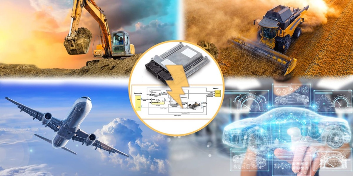
Simulink system modeling plays a critical role in modern engineering design, especially in domains such as automotive, aerospace, robotics, and industrial automation. It is a powerful graphical environment developed by MathWorks that enables engineers to model, simulate, and analyze complex dynamic systems. By integrating seamlessly with MATLAB, Simulink provides an efficient platform for multi-domain simulation and Model-Based Design (MBD), helping engineers visualize system behavior and validate performance long before physical prototypes are built.
1. Introduction to Simulink System Modeling
Simulink provides a visual, block-diagram-based interface for modeling systems that include mechanical, electrical, control, and signal processing components. Unlike traditional coding-based simulation, Simulink uses interconnected blocks to represent mathematical equations, physical components, and data flow, making system design more intuitive and efficient.
This approach allows engineers to test and optimize designs virtually, reducing development time and cost. It also ensures higher reliability since errors can be identified and corrected early in the design cycle.
Simulink is widely used across industries for developing embedded systems, control algorithms, and real-time simulations. Whether it’s an engine control unit, robotic arm, or renewable energy system, Simulink helps engineers analyze how systems interact and behave under varying conditions.
2. Key Features of Simulink System Modeling
Simulink offers several advanced features that make it indispensable for engineers and researchers:
a. Graphical Modeling Interface
Simulink’s drag-and-drop interface allows engineers to build models visually by connecting functional blocks. This graphical representation simplifies complex systems and improves understanding among multidisciplinary teams.
b. Multi-Domain Simulation
Systems often involve mechanical, electrical, hydraulic, and control components working together. Simulink, combined with Simscape, allows simulation across these domains, ensuring integrated system modeling.
c. Integration with MATLAB
Simulink integrates seamlessly with MATLAB, enabling engineers to use MATLAB functions, scripts, and data analysis tools directly within models. This integration allows advanced customization and automated workflows.
d. Real-Time Simulation and Code Generation
Using tools such as Simulink Coder and Embedded Coder, engineers can automatically generate C/C++ code from models for real-time applications and embedded hardware deployment. This significantly accelerates development and reduces manual coding errors.
e. Parameter Tuning and Optimization
Simulink allows dynamic tuning of parameters while simulations are running. This helps in identifying the best design configurations through iterative optimization and sensitivity analysis.
f. Model Verification and Validation
Simulink provides built-in tools for verifying system behavior, testing requirements, and validating control logic. Features like Simulink Test and Requirements Toolbox support model-based verification workflows.
3. Benefits of Using Simulink for System Modeling
Simulink offers numerous advantages throughout the engineering design lifecycle:
a. Early System Validation
Engineers can simulate and analyze the entire system before hardware is built, reducing prototype costs and development time.
b. Improved Accuracy and Reliability
By using mathematical and physical modeling, engineers can predict real-world behavior more accurately, minimizing design errors.
c. Accelerated Development through Model-Based Design
Simulink supports the Model-Based Design approach, where models serve as the central reference for design, testing, and implementation. This approach streamlines workflows and enhances traceability from concept to production.
d. Seamless Hardware Integration
Simulink models can be deployed directly onto hardware such as microcontrollers, FPGAs, and real-time simulators, bridging the gap between simulation and physical testing.
e. Efficient Collaboration
The graphical environment makes it easier for multidisciplinary teams—mechanical, electrical, and software engineers—to collaborate effectively on a unified platform.
4. The Process of Simulink System Modeling
The typical workflow for developing a system model in Simulink involves several key stages:
1. System Definition:
The process begins with defining the overall system requirements, identifying inputs, outputs, and control logic.
2. Model Creation:
Engineers build a block diagram model in Simulink using pre-built libraries or custom subsystems. Each block represents a mathematical function, sensor, actuator, or physical process.
3. Simulation and Analysis:
Once the model is built, simulations are run to study system dynamics under various scenarios. Engineers analyze time responses, stability, and performance metrics.
4. Optimization and Parameter Tuning:
Using optimization tools, design parameters are fine-tuned to achieve desired performance goals, such as reduced overshoot or improved energy efficiency.
5. Validation and Testing:
Engineers validate the model against real-world data and system requirements to ensure accuracy. Simulink’s testing tools help identify inconsistencies or design flaws.
6. Code Generation and Deployment:
For embedded systems, models are automatically converted into production-ready C/C++ code using Embedded Coder. This code can then be deployed on target hardware for real-time execution.
5. Applications of Simulink System Modeling
Simulink is used across numerous industries to model and simulate systems that demand precision, efficiency, and real-time control:
a. Automotive Industry:
Simulink is extensively used for developing engine control units (ECUs), vehicle dynamics, ADAS (Advanced Driver Assistance Systems), and electric vehicle powertrain control.
b. Aerospace and Defense:
It supports flight control systems, navigation algorithms, and aircraft dynamics modeling. Engineers can simulate conditions such as turbulence, thrust variation, and stability.
c. Robotics and Automation:
Simulink helps design robotic kinematics, motion control algorithms, and sensor integration, ensuring optimal path planning and movement accuracy.
d. Energy Systems:
Engineers use Simulink to model renewable energy systems, smart grids, and power electronics to enhance energy efficiency and reliability.
e. Industrial Machinery:
Simulink aids in developing advanced control systems for manufacturing equipment, predictive maintenance, and process automation.
6. Advanced Simulink Toolboxes
To extend its capabilities, Simulink offers various specialized toolboxes:
Simscape: For modeling physical systems including mechanical, hydraulic, and electrical components.
Stateflow: For designing event-driven systems and state machines.
Simulink Control Design: For tuning and analyzing control systems.
Simulink Test: For automated model testing and validation.
Embedded Coder: For generating optimized code for embedded hardware.
These add-ons make Simulink a complete ecosystem for designing, testing, and deploying engineering systems.
7. The Role of Simulink in Model-Based Design (MBD)
Model-Based Design is a methodology that integrates modeling, simulation, and code generation into a unified workflow. In MBD, Simulink serves as the central environment where:
Models act as the single source of truth for design.
Engineers perform simulations to refine performance.
Verified models are automatically translated into deployable code.
This eliminates manual coding errors, ensures consistency, and accelerates time-to-market. Industries adopting MBD with Simulink have reported significant improvements in efficiency, cost savings, and innovation.
8. The Future of Simulink System Modeling
As technology evolves, Simulink continues to expand its capabilities to support emerging engineering domains. With growing trends in AI, machine learning, and digital twins, engineers can now integrate predictive models and intelligent algorithms directly into Simulink environments.
Additionally, with cloud-based collaboration and high-performance computing integration, large-scale system simulations are becoming faster and more accessible. These advancements make Simulink an indispensable tool for next-generation engineering solutions.
9. Conclusion
Simulink system modeling is transforming how engineers design, test, and implement complex systems. By offering a powerful, integrated platform for modeling, simulation, and code generation, it enables faster innovation, greater accuracy, and reduced development costs.
From automotive control systems to renewable energy management, Simulink empowers engineers to visualize, validate, and optimize designs long before production—ensuring reliability and performance in real-world applications.


