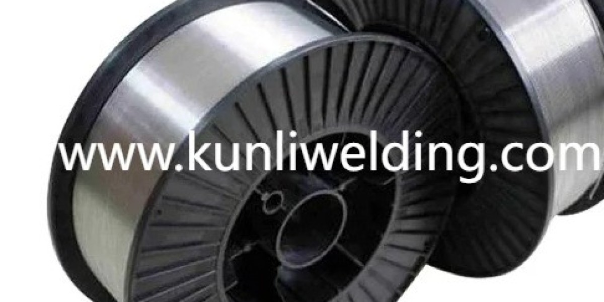
Robotic welding cells demand steady consumables and careful setup, and Aluminum Welding Wire ER5356 often enters the conversation when teams seek reliable feed and predictable bead appearance in automated environments. This alloy's flow characteristics and mechanical profile make it a common choice for production lines that weld aluminum panels and structural brackets, but getting consistent feedability in robotic rigs requires a set of practical adjustments and habits.
Start by matching spool and drive hardware to the application. A rigid, well wound spool and drive rolls shaped for non slipping contact reduce slippage and the chance of bird nesting at the feeder. Where long feed paths exist, a low friction liner and careful routing keep the wire moving smoothly from spool to torch. Robotic integrators who tune spool orientation and minimize sharp bends in the feed path report fewer interruptions and steadier arc starts.
Control of drive roll pressure and roll profile is another small lever with big impact. Too light and the rolls slip; too heavy and the wire deforms and jams. Match the roll groove to the wire diameter and check for wear regularly so the feeding force stays consistent. Regular inspection of contact tips and liners prevents gradual degradation that shows up as inconsistent wire speed or erratic arc behavior during long production runs.
Wire selection and handling still matter even in fully automated cells. ER5356 tends to have a firmer spool stiffness than some other alloys which can help feeding in push only systems, but it also benefits from clean handling so that contamination does not introduce feeding friction. Store spools where humidity and dust are controlled and unspool a short length to verify surface finish before loading into the cell. These habits reduce the odds of stoppages and lower rework at downstream stations.
Tune the robot program to match filler behavior. Adjust travel speed and wire feed settings in small increments during setup runs to find a stable puddle that minimizes spatter and helps the bead form evenly. For long seams use overlapping test passes under production conditions so you understand how heat input and travel combine to affect distortion and final appearance. Document the final parameter set so the program can be reproduced across cells and shifts.
Maintenance cadence for automated feeders should be proactive. Replace liners, clean or swap drive rolls and inspect spool flanges on a regular schedule rather than waiting for a stoppage to force action. Simple checklists that operators run at shift change preserve a steady feed rate and reduce the number of unexpected pauses. When multiple cells use the same wire type, share the checklist so best practices are captured and repeated across the shop.
Consider the whole system when troubleshooting. If the cell shows intermittent feed faults, separate the problem into spool hardware feed path and program timing checks. A practiced sequence of substitution tests helps isolate whether the culprit is a worn liner, a misaligned roll set, or a program drift in travel speed. Many integrators find that running a short controlled feed test with a known good spool quickly reveals the weak link.
Finally, partner selection and supplier support ease qualification. Suppliers that offer consistent winding, clear packaging notes and sample spools for trial runs shorten the path from setup to reliable production. When vendors provide handling guidance tailored to robotic feed systems, shops can avoid common pitfalls and get cells running with fewer start up issues. For teams ready to tune robotic cells for stable aluminum welding, review product details and handling guidance at the manufacturer pages on www.kunliwelding.com .